


A module assembler for a European EV battery pack had a recurring quality issue. Bolts connecting individual cells to the busbar kept loosening after a few thousand miles. Their vehicle log showed intermittent voltage drops, and thermal imaging revealed connectors running 15°C hotter than design spec. Tightening bolts repeatedly didn’t solve the root cause; vibration loosens hardware, and thermal cycling changes contact pressure. The assembler switched to a flexible busbar – a press‑bonded, multi‑layer laminated conductor with no bolts, no lugs, and no separable interfaces at the module level.
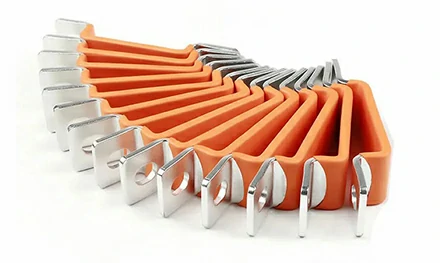
A flexible busbar is constructed from multiple thin layers of electrolytic copper foil, each layer between 0.1mm and 1mm thick, press‑bonded at the ends to form a solid termination while leaving the central section flexible. The conductor can be bent, folded, and shaped to follow the exact geometry of a battery module or power distribution cabinet, eliminating separate jumpers, cables, and terminal adapters. This guide explains why laminated construction outperforms braided copper on impedance and heat dissipation, how insulation (PE heat‑shrink or PVC dip‑coating) affects UL94 V‑0 certification and temperature rating, where the 10,000‑cycle bending endurance specification comes from, and why salt spray testing (240‑400 hours) determines whether a busbar belongs in a coastal wind turbine or a desert solar farm.
Braided copper busbars are made from many thin copper strands woven together, then pressed flat at the ends. They are flexible and relatively inexpensive, but they have two drawbacks for high‑current applications. First, the woven structure creates air gaps between strands, reducing the effective cross‑sectional area for current flow. Second, the strands can break individually under repeated flexing, progressively increasing resistance until the busbar fails.
The laminated flexible busbar solves both problems. The copper foils are stacked solidly at the contact ends, where the busbar is pressed under high force to create a monolithic copper block. There are no air gaps. The current density across the termination is uniform. The flexible section retains the individual foils, which slide against each other during bending, relieving mechanical stress. No single foil carries the full bending load; the stress is distributed.
| Feature | Laminated Copper | Braided Copper | Welded Cable Assembly |
|---|---|---|---|
| Contact resistance | Very low (press‑bonded) | Moderate (compressed strands) | Low (crimped lugs) |
| Flexibility | Moderate (foils slide) | High (strands move freely) | Very low (cable bends, not lugs) |
| Vibration resistance | Excellent (no loose parts) | Poor (strands break over time) | Fair (bolt loosening risk) |
| Impedance at high frequency | Low (solid cross‑section) | High (skin effect on strands) | Moderate |
| Typical application | EV batteries, power electronics | Grounding straps, low‑current | General power distribution |
The impedance advantage of laminated busbars becomes significant at high frequencies. In an EV inverter, switching at tens of kHz, laminated copper’s uniform cross‑section provides a lower impedance path than braided copper, reducing energy loss and heat generation.
A flexible busbar must be insulated to prevent short circuits between phases or to ground. Three insulation methods are common, each with a different performance envelope.
Polyethylene heat‑shrink tubing is applied over the busbar after forming, then heated to shrink tightly around the conductor. It provides a uniform, flexible insulation layer with good abrasion resistance. PE is rated for temperatures up to 105°C and meets UL94 V‑2 or V‑0 depending on formulation. The wall thickness is typically 0.5‑1mm. PE heat‑shrink is the standard choice for EV battery busbars.
The busbar is dipped into liquid PVC, then cured. The coating adheres directly to the copper, sealing the edges of the laminated foils. PVC is more flexible than PE heat‑shrink but has a lower temperature rating (typically 80‑90°C). It is used in lower‑current applications where the busbar does not get hot.
Nomex (aramid paper) is wrapped around the busbar and impregnated with varnish. It has the highest temperature rating (220°C) and excellent dielectric strength, but it is less flexible and more expensive. Nomex is used in high‑temperature railway and industrial applications.
The insulation system is also where the UL94 V‑0 flammability rating applies. V‑0 means the material self‑extinguishes within 10 seconds after ignition, with no flaming drip. For a busbar installed in a battery pack, meeting V‑0 is a safety requirement, not an option.
The flexible section of a laminated busbar is designed to bend during installation and, in some applications (e.g., door hinges on a train or movable battery trays), during operation. The manufacturer specifies a bending endurance of over 10,000 cycles at a 90° bend radius.
The test method: a sample busbar is clamped at one end, and the flexible section is bent 90° to one side, then returned to straight, then bent 90° to the opposite side. One cycle is a full back‑and‑forth motion. The busbar is cycled at a rate of one bend per second. After 10,000 cycles, the busbar is inspected for cracks or foil separation and retested for resistance. A passing busbar shows no visible damage and less than a 5% increase in resistance.
For most EV applications, 10,000 cycles is a very conservative requirement. The busbar is installed once and does not move again. The endurance spec is primarily for applications where the busbar must survive the assembly process (bending into shape) and occasional maintenance access.
A busbar installed in a battery cabinet on a coastal wind farm or an electric vessel will be exposed to salt‑laden air. Copper corrodes rapidly in a salt environment. The corrosion creates a high‑resistance oxide layer that heats up under load.
The salt spray test (ASTM B117) exposes the busbar to a 5% sodium chloride solution mist at 35°C. For standard indoor applications, 96 hours of salt spray testing is typical. For coastal and marine applications, the specification increases to 240‑400 hours. A busbar that passes 400 hours of salt spray shows no red rust on the copper edges and no blistering of the insulation.
The test is conducted with the busbar in its finished condition, including the insulation and any exposed copper at the termination ends. The insulation must remain intact, and the copper terminations must not show corrosion that would affect conductivity.
The flexibility of laminated copper busbars makes them suitable for a wide range of electrical connections.
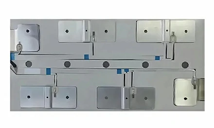
EV battery modules – Connecting cells in series and parallel. The busbar replaces multiple welded or bolted cell connectors, reducing assembly time and eliminating loose‑bolt failure modes.
Power distribution cabinets – Connecting circuit breakers, fuses, and terminals. The flexible busbar can be routed around enclosures without custom‑shaped rigid busbars.
Inverter and converter connections – Busbars between IGBT modules and DC‑link capacitors. Laminated construction minimizes stray inductance, which reduces voltage spikes during switching.
Railway and tram power systems – Flexible connections between power modules and battery banks, where vibration from tracks would loosen bolted hardware.
Solar combiner boxes – Connecting multiple string inputs to a single output. The flexible busbar simplifies field assembly and reduces the number of compression terminals.
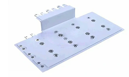
Each application may require a different insulation type (PE for EV, Nomex for high‑temperature railway, PVC for solar combiner boxes) and different bend specifications. The termination ends can be manufactured with pre‑drilled holes (for bolted connection to the next component) or as bare pads for welding or soldering.
The base material of the flexible busbar is electrolytic copper foil (ASTM B152/C11000 grade). The foil has a purity of 99.9% copper, with a conductivity rating of 100% IACS (International Annealed Copper Standard). The foil thickness range for flexible busbars is typically 0.1mm to 1mm per layer. Thinner foils increase flexibility but reduce current capacity. Thicker foils carry more current but are stiffer.
The assembly process: individual foils are cut to length, stacked to the required cross‑sectional area (e.g., 10 layers of 0.3mm foil for 100mm² total cross‑section), then pressed at the termination ends under high pressure and sometimes heat to bond the layers together. The bonded area becomes a solid copper block. The flexible section is left unbonded, allowing the foils to move independently.
The number of layers determines the flexibility. A busbar with 20 layers of 0.1mm foil is more flexible than a busbar with 5 layers of 0.4mm foil, even though the total cross‑section (2mm²) is the same. The specification for the project should include the required flexibility (minimum bend radius) in addition to current capacity.
Laminated flexible busbars have a preferred bend direction. Bending across the width of the busbar (around the axis parallel to the long edge) is easier and safer than bending flatwise (around the axis perpendicular to the width). The datasheet typically lists a minimum bend radius for both directions. Exceeding the minimum radius can cause individual foils to crack at the edge. The field solution: train installers to bend along the natural flex direction and use a forming tool for complex shapes.
The solid press‑bonded termination pads are soft copper. Using a torque wrench set for a steel terminal will deform the copper, reducing contact area and increasing resistance. The recommended torque for copper busbar terminations is typically 30‑50% lower than for steel. The correct installation method: use a torque wrench set to the value specified in the drawing, and use a flat washer under the bolt head to distribute the load.
PE heat‑shrink can be nicked by sharp edges during handling. A small cut in the insulation may not cause an immediate failure, but over time moisture will wick through the cut and corrode the copper underneath. The inspection standard: before installation, run a finger over the entire insulation surface. Any cut that catches a fingernail is a reject. Insulation repair kits (heat‑shrink patches) are available for field use, but replacement is preferred.
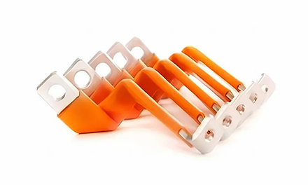
[Image: Flexible busbar bent into an S‑shape, showing the solid termination pads at both ends and the flexible foil section between, with PE heat‑shrink insulation covering the entire length]
Haiyan New Energy (Zhejiang Haiyan New Energy Technology Co., Ltd.) has manufactured flexible busbars for the EV, energy storage, and industrial power markets. The product line includes laminated copper busbars with PE, PVC, or Nomex insulation, as well as braided copper connectors, silver‑plated busbars, and insulated cables. The company serves customers in China, Europe, and North America, with production capacity for custom lengths, cross‑sections, and termination geometries.
The flexible busbar is designed to replace multiple components in a power stack: cables, lugs, insulation sleeving, and cable ties. The reduction in part count simplifies assembly, reduces quality escapes, and cuts the number of failure points. The busbar is manufactured to ISO 9001 standards, and test reports (salt spray, insulation resistance, and bending endurance) are provided with each batch.
For a flexible busbar that eliminates the bolted connections responsible for thermal events in EV battery packs, the laminated copper design from Haiyan delivers press‑bonded terminations, UL94 V‑0 insulation, 10,000‑cycle bending endurance, and salt spray resistance up to 400 hours.
[Request a quote from Haiyan New Energy]
Contact Haiyan New Energy with your current rating (A), maximum operating temperature, and required bend radius to receive a laminated flexible busbar drawing and cost estimate.
GET A QUOTE