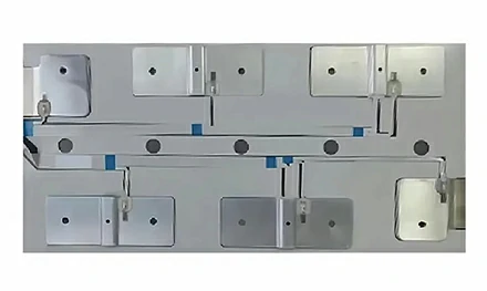


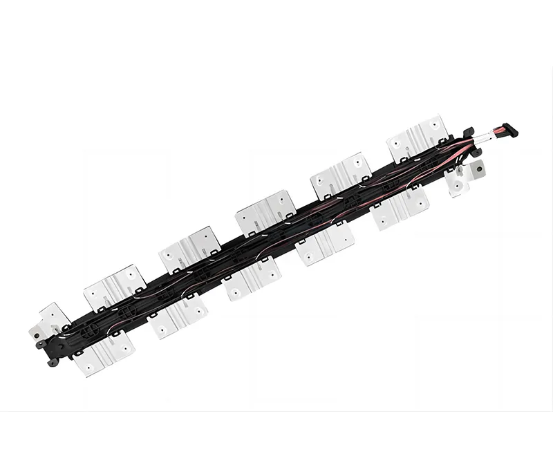
An on‑site failure at a solar farm in Spain. A DC combiner box was opened for routine cleaning. The inspector found carbon tracking marks inside the enclosure – a tell‑tale sign of partial discharge between an uninsulated copper busbar and the grounded metal wall. The thin layer of dust on the busbar's surface had become conductive under humidity, and after months of leakage current, the tracking had carbonized the insulation path. The entire combiner box needed replacement, and the downstream inverter had been damaged by the fault. The original busbar was bare copper, installed before the insulation requirement was added to the specification.
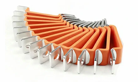
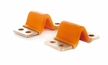
The solution was an insulated flexible busbar – a laminated copper conductor fully coated with a UL94 V‑0 rated polyethylene (PE) heat‑shrink or PVC dip‑coating. The insulation eliminates the air gap that allows tracking. It also covers the cut edges of the laminated foils, which are otherwise the point where corrosion starts in humid environments. This article examines three aspects of insulated flexible busbar selection that determine long‑term reliability: how the insulation thickness (typically 0.5‑1mm) affects the comparative tracking index (CTI) and the application's pollution degree, why the insulation material choice (PE vs PVC vs Nomex) depends on the operating temperature and UV exposure, and how the factory's insulation‑withstand test (2.5kV or 5kV DC) ensures that the busbar will not fail after years of thermal cycling.
Insulation on an insulated flexible busbar serves two purposes: it provides electrical isolation between phases and to ground, and it protects the copper from moisture and chemical corrosion. The three common insulation systems have distinct performance envelopes.
Polyethylene heat‑shrink tubing is the standard choice for EV battery packs and general power distribution. PE is specified because it has high dielectric strength (20‑30 kV/mm), good flexibility, and meets UL94 V‑0 flammability at appropriate wall thickness. The shrink ratio is typically 2:1 or 3:1, allowing it to conform tightly to the busbar shape, including the transition from the flexible foil section to the solid termination pads. PE is rated for a continuous operating temperature of 105°C, which covers the majority of battery and power electronics applications. The wall thickness is typically 0.5‑1.0mm, sufficient to withstand 600V DC systems (common in EV batteries and solar inverters).
PVC is applied by dipping the busbar into liquid PVC, then curing in an oven. It adheres directly to the copper, sealing the edges of the laminated foils. PVC is more flexible than PE and can be applied in uniform thicknesses down to 0.3mm. However, PVC has a lower continuous temperature rating (80‑90°C) and lower dielectric strength than PE. It is used in lower‑current applications where the busbar does not heat significantly, such as control cabinets and low‑power distribution. PVC also has a lower tracking resistance (CTI) than PE, making it less suitable for high‑humidity environments.
Nomex (aramid paper) is wrapped around the busbar and impregnated with varnish. It has the highest temperature rating (220°C) and excellent dielectric strength, but it is more expensive and less flexible. The paper is applied dry, then the assembly is dipped in varnish and cured. Nomex is specified for high‑ambient environments, such as traction inverters on electric trains, where the busbar may be exposed to 120‑150°C. It also provides arc‑resistance properties that PE and PVC do not.
| Insulation Type | Temp Rating | Flexural Modulus | CTI (Tracking Index) | Typical Application |
|---|---|---|---|---|
| PE heat‑shrink (UL94 V‑0) | 105°C | Medium | 600V+ | EV batteries, solar combiner boxes |
| PVC dip‑coating (UL94 V‑2 or V‑0) | 80‑90°C | Low (flexible) | 400‑500V | Low‑power distribution, indoor cabinets |
| Nomex paper + varnish | 220°C | High (stiff) | 600V+ | Railway traction, high‑temp industrial |
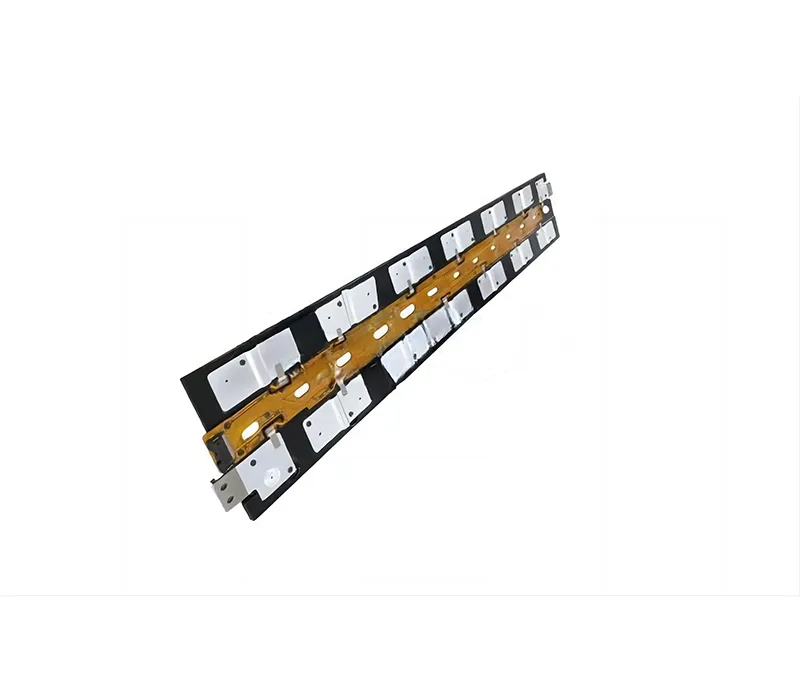
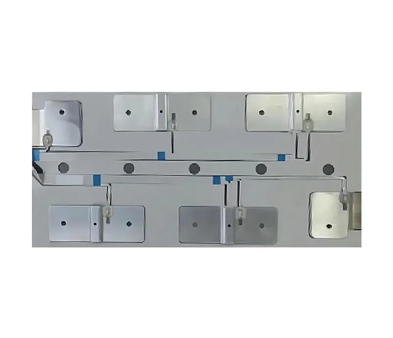
A laminated flexible busbar is made from multiple layers of copper foil. The cut edges of those foils are exposed at the sides of the busbar. If the edge is not sealed, moisture wicks into the gap between the foils through capillary action. Once moisture is inside the laminate, galvanic corrosion begins, and the bond between layers weakens. The resistance increases, the busbar heats up, and the cycle accelerates.
An insulated flexible busbar from Haiyan covers the edges completely. The heat‑shrink tubing or dip‑coating wraps around the entire profile of the busbar, sealing the edges. For double‑wall heat‑shrink with an adhesive inner layer, the adhesive flows when heated and fills any remaining gaps at the cut edge. For PVC dip‑coating, the material flows into the interstices between foils before curing.
The edge seal is tested by salt spray (ASTM B117). A busbar that has been properly edge‑sealed shows no corrosion at the cut ends after 240‑400 hours of exposure. An unsealed busbar will show green copper chloride deposits within 96 hours, indicating that moisture has penetrated the laminate.
Insulation materials gradually degrade under surface leakage current. When moisture and dust accumulate on the surface of an insulated busbar, a conductive path can form. The voltage at which this path becomes permanent and carbonizes the insulation is the comparative tracking index (CTI). For applications where the busbar is installed in a combiner box on a solar farm, where dust and high humidity are present, a low CTI insulation can fail after a few years.
UL94 V‑0 rated PE typically has a CTI of 600V or higher, meaning it can withstand 600V AC without tracking. PVC has a CTI of 400‑500V, depending on the plasticizer content. For PV systems operating at 1000V DC or 1500V DC, the insulation must be specified to meet the system voltage plus a safety margin. Haiyan uses PE grades with a CTI of >600V, which meets the requirements for 1000V DC systems where the busbar is installed in pollution degree 2 or 3 environments.
The CTI is measured according to IEC 60112. A 600V CTI rating means the insulation passed 100 drops of electrolyte at 600V without tracking. This performance is not achieved by any insulating material; it requires careful material selection and quality control over the compounding of the PE resin.
The factory test for an insulated flexible busbar (主词加粗第4次) includes a dielectric withstand test (also called a hipot test). The busbar is placed in a test fixture, and a high voltage is applied between the conductor (all foils shorted together) and a conductive pad pressed against the insulation surface. The test voltage for a 600V‑rated busbar is typically 2.5kV DC for 60 seconds. For 1000V DC rated systems, the test voltage is 4‑5kV DC.
The pass/fail criterion is zero dielectric breakdown. There must be no arcing, no sparking, and no current leakage above the test threshold (typically 5‑10mA). After the 60‑second hold, the test voltage is reduced to zero, and the busbar is visually inspected.
A busbar that passes the hipot test is guaranteed to have no pinholes in the insulation and no bridging between layers of the laminated copper. This test is performed on 100% of production units, not just on a sample batch.
The insulation system on a flexible busbar must remain intact during bending. If a PE heat‑shrink tube is bent too sharply, the material on the outside of the bend stretches and can thin, while the material on the inside of the bend wrinkles or may crack.
The minimum bending radius for an insulated flexible busbar is typically specified as 10‑15 times the busbar thickness. For a busbar that is 5mm thick (including insulation), the minimum bend radius is 50‑75mm. Bending to a smaller radius risks damaging the insulation. For applications where the busbar must fit into a tight space, a custom shape can be formed at the factory (pre‑bent) rather than field‑bent, ensuring that the insulation is not stressed.
Field bending instruction: use a forming tool with a smooth radius, not a sharp edge. Do not bend the busbar back and forth repeatedly; this work‑hardens the copper and can crack the foils. The insulation should be visually inspected after bending for signs of cracking, whitening (stress marks), or separation from the copper.
[Image: Insulated flexible busbar bent to a 90° radius on a mandrel, showing the smooth outer surface of the PE insulation without wrinkles or cracks]
The insulation life of a flexible busbar is temperature‑dependent. PE rated for 105°C continuous operation has a thermal aging life of approximately 10 years at 105°C. At 85°C, the life extends to 20‑30 years. At 65°C, it is effectively indefinite for the life of the equipment.
The Arrhenius model estimates that every 10°C reduction in operating temperature doubles the insulation life. For a busbar in an EV battery pack that sees peak temperatures of 85°C during fast charging but averages 45°C over the vehicle’s life, the insulation is not a life‑limiting component. However, for a busbar in a solar combiner box in the desert, where the enclosure can reach 70°C daily, the insulation should be monitored.
The dielectric withstand test can be repeated at service intervals (e.g., every 5 years). A busbar that passes a 2.5kV hipot test is still safe to operate. A busbar that shows a drop in insulation resistance (measured with a megohmmeter) or fails hipot should be replaced.
An installer trying to remove a section of heat‑shrink insulation at the termination may use a utility knife, scoring the insulation and cutting partially into the copper. The nick creates a stress riser; under thermal cycling, the insulation may crack from that point. The correct method: use a heat‑shrink removal tool (a hooked blade that cuts only the tubing) or a pair of smooth‑jawed pliers to peel the shrink back after a small cut is started with a scriber.
Field bending without a radius gauge can easily exceed the minimum bend radius, wrinkling the inside of the insulation. Even if the insulation does not crack immediately, the wrinkled area has a thinned wall and reduced dielectric strength. The rule: if the bend looks sharp enough to feel a crease by hand, it is too tight.
A cut through the insulation down to the copper exposes the busbar to moisture and creates a discharge path. The field inspection should include a 100% visual inspection of each busbar before installation. Any cut longer than 2mm or any hole that exposes copper is a reject. Small scratches that do not reach the copper can be covered with a dab of silicone sealant or a patch of self‑amalgamating tape.
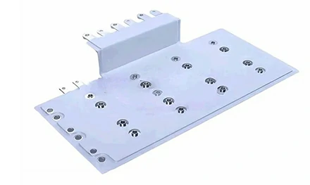
Haiyan New Energy manufactures insulated flexible busbars for the EV, energy storage, solar, and industrial power markets. The company produces busbars from 0.1‑1mm copper foils, laminated to cross‑sections up to 300mm². Insulation options include PE heat‑shrink (UL94 V‑0, 105°C, CTI>600V), PVC dip‑coating (80‑90°C), and Nomex paper wrap (220°C). Each busbar is hipot‑tested at 2.5kV DC (or customer‑specified voltage) before shipment, and salt spray test reports (up to 400 hours) are provided on request.
Haiyan also supplies bare laminated busbars (without insulation) for applications where the busbar is installed in an enclosure that already provides isolation. The insulated version is used where the busbar may contact live surfaces or where external moisture is present.
For an insulated flexible busbar that eliminates the phase‑to‑ground tracking failures that shut down solar farms and battery packs, Haiyan’s PE‑coated laminated copper design delivers UL94 V‑0 flammability, 600V+ CTI, 400‑hour salt spray resistance, and factory dielectric testing.
[Request a quote from Haiyan New Energy]
Contact Haiyan with your system voltage (600V, 1000V, or 1500V DC), operating temperature range, and required bend radius to receive an insulated flexible busbar drawing and test report.
GET A QUOTE