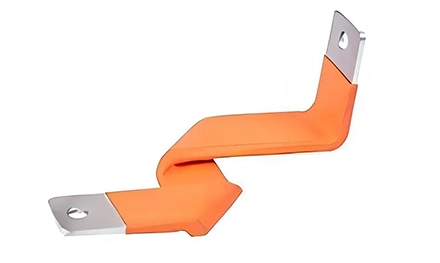


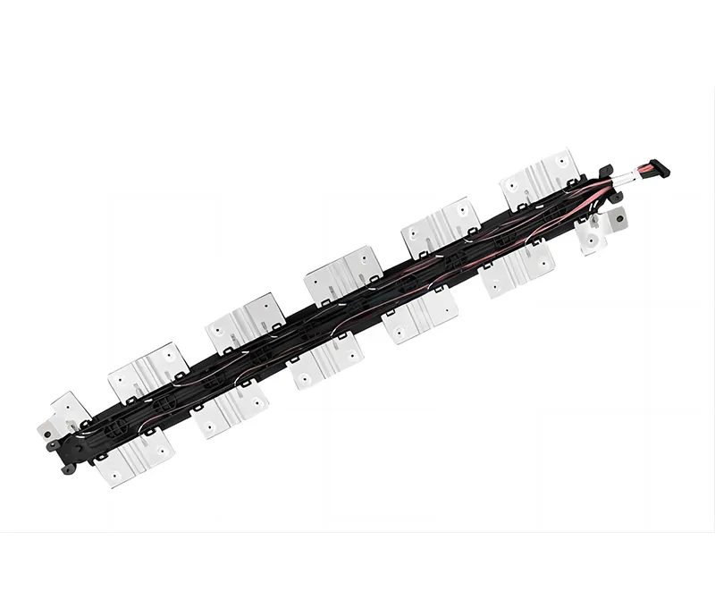
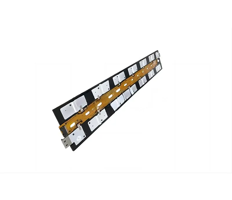
Yes, in many high-density power cabinets, a Composite laminated busbar can replace a multi-cable harness with a single bolted assembly. The laminated structure cuts stray inductance below 50 nH/m by stacking positive and negative copper layers against ultra-thin dielectric films, and it reduces assembly time compared with hand-routed heavy cable. This article explains how the layer stack cancels inductance, what the manufacturing process contributes to long-term reliability, and where flexible flat braid connections fit when the layout demands movement.
Stray inductance in a power loop is proportional to the area enclosed by the current path. In a conventional cable harness, the positive and negative conductors run separately, enclosing a large loop area that captures magnetic flux. In a laminated busbar, the positive and negative copper plates are stacked with only a thin dielectric film between them. Current flows in opposite directions through adjacent layers, so their magnetic fields oppose each other and largely cancel.
The result is a loop inductance that stays under 50 nH/m across the busbar length. That low inductance suppresses the voltage spike that appears across the IGBT when it interrupts current, reducing the need for higher-voltage-rated switches and the cost that comes with them.
The conductors are flat C1100 ETP copper strips ranging from 0.5 mm to 5.0 mm in thickness. A flat profile distributes current more uniformly across the cross-section than a round cable, which reduces AC impedance at the switching frequencies where skin effect pushes current toward the conductor surface. The flat geometry also gives the busbar a lower profile than a cable bundle, freeing vertical space inside dense cabinets.
| Parameter | Composite Laminated Busbar (Typical) |
|---|---|
| Conductor material | C1100 ETP copper |
| Copper thickness | 0.5–5.0 mm |
| Layer count | Up to 6 layers |
| Stray inductance | <50 nH/m |
| Dielectric withstand | 3.0 kV AC, 1 min |
| Continuous current (ΔT <30°C) | 600 A |
| Partial discharge | 100% tested |
| Working temperature | -40°C to 105°C |
| Flammability | UL94 V-0 |
The copper plates and dielectric films are stacked and cured in a hydraulic vacuum press at calibrated temperature ramps. The vacuum removes air from between the layers before the adhesive cures, so the finished busbar has no voids inside the insulation stack. Voids are where partial discharge starts—a trapped air pocket inside the dielectric sees a much higher electric field than the surrounding material and can erode the insulation over time.
That’s why the manufacturer performs 100% partial-discharge testing before dispatch. Each busbar is checked for the discharge signature that would indicate a void or a delamination. For a 800V DC architecture or a high-dv/dt inverter, that test is the difference between a busbar that lasts the life of the cabinet and one that fails after a few thousand thermal cycles.
The copper plates are stamped with positional tolerances held within ±0.05 mm . That precision keeps the terminal mounting holes aligned across all the stacked layers, so a single bolt passes through the entire stack without reaming or misalignment. The edges are deburred mechanically and cleaned ultrasonically before lamination, removing the micro-burrs that could otherwise puncture a thin dielectric film during a high-voltage event.
A laminated busbar’s current rating is not a single number—it’s tied to the allowable temperature rise. The design target for this platform is a steady-state temperature rise under 30°C at 600 A continuous current, verified through thermocouple logging in an enclosed cabinet simulation. That test condition matters because a busbar that runs cool on a bench can run hot inside a sealed enclosure where the only cooling path is conduction to the chassis.
The flat copper geometry helps here as well. A wide, thin conductor has more surface area per unit of cross-section than a round cable, so heat escapes to the surrounding air and to the cabinet walls more readily. The dielectric films—DuPont PET or epoxy powder coatings—are selected to withstand the operating temperature without softening or flowing.
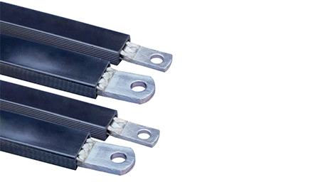
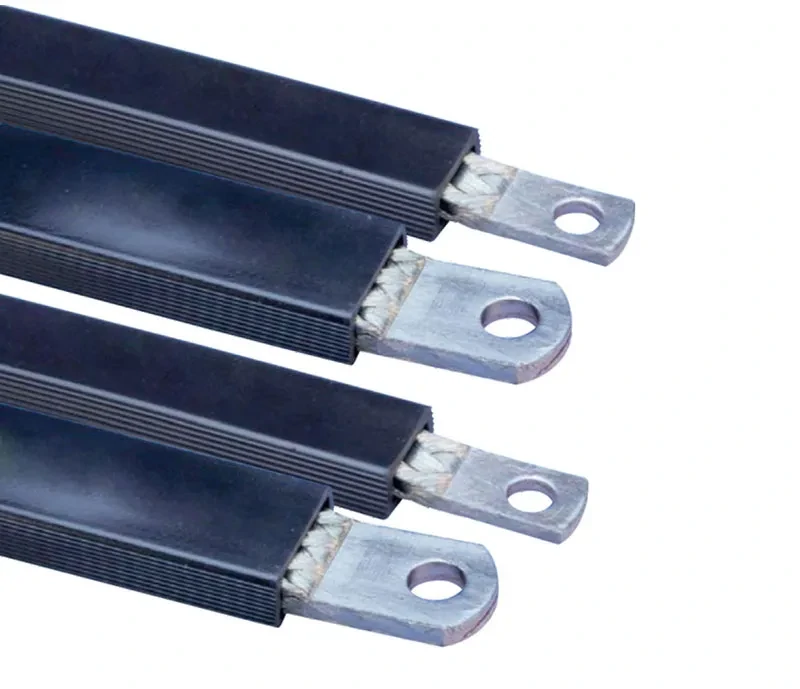
A rigid laminated busbar is efficient along a straight run, but it cannot absorb vibration or accommodate a terminal that sits at a slightly different angle. That’s where Flat Copper Braid in the IBSB and IBSBR configurations enters the assembly. The braid is a flexible conductor made from 0.15 mm electrolytic copper wire, woven into a flat profile with integral palms pressed at each end. The braid bolts to the rigid busbar on one end and to the breaker or module terminal on the other, absorbing tolerance stack-up and vibration without adding a separate cable lug.
The IBSB/IBSBR range covers 25 to 240 mm² cross-section and 80 A to 630 A, with lengths from 230 mm to 1030 mm . The insulation is a self-extinguishing PVC rated to 105°C, with a dielectric strength of 20 kV/mm . The integral palm construction welds the braid directly into a solid copper block, so there is no crimped lug to loosen or corrode.
The braided construction resists the vibration that a rigid bar would transmit to its mounting bolts. In a motor drive cabinet or a rail traction application, that flexibility prevents the terminal from fatiguing under constant movement. The integral palm also eliminates the moisture path that can enter a crimped lug by capillary action and corrode the wire bundle over years of service.
A Composite laminated busbar system that pairs rigid laminated runs with flexible flat braid terminations covers both the low-inductance distribution path and the tolerance-absorbing connection point. That combination is why the platform is specified in UPS, telecom base stations, motor drives, and energy storage racks where assembly time and long-term reliability both matter.
The copper thickness range of 0.5–5.0 mm per layer defines the current capacity, but the number of layers and the total cross-section determine the final rating. For a 600A continuous duty with a 30°C rise, the stack is built to that target through thermal simulation, not by simply adding copper. If your continuous current exceeds 600A, confirm the layer configuration and the expected temperature rise inside your specific cabinet volume, because the enclosure thermal resistance changes the derating.
Ask for the partial-discharge test report for each busbar. The test should be performed at a voltage above the operating voltage—typically the dielectric withstand test at 3.0 kV AC for one minute is used as the screening condition. A busbar that passes the withstand test but shows partial discharge activity at a lower voltage may still degrade over time, especially in a high-humidity environment. The 100% testing requirement is the practical check.
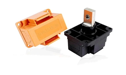
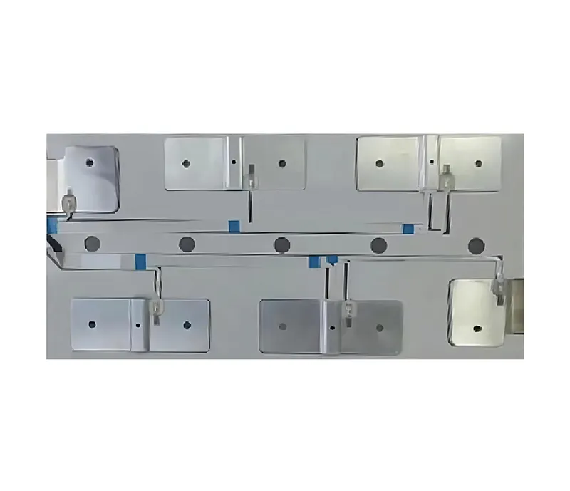
The laminated busbar supports folded tabs, PEM clinch nuts, welded studs, and threaded compression blocks integrated directly into the outer copper layers. If the connection point needs to absorb movement, specify a flat braid (IBSB/IBSBR) with an integral palm that bolts to the busbar and to the terminal. Confirm the palm hole pattern and the bolt torque against the mating component before finalizing the drawing.
A laminated busbar is a rigid, multi-layer assembly designed for low-inductance power distribution along a defined path. A flat copper braid is a flexible conductor used for connections that need to absorb vibration, tolerance, or movement. The two are complementary—the busbar handles the distribution backbone, the braid handles the flexible terminations.
In many high-density cabinets, yes. A laminated busbar replaces a multi-cable harness with a single bolted assembly, eliminating wiring errors and reducing assembly time. The documentation for this platform cites a 70% reduction in cabinet assembly man-hours compared to hand-bent heavy copper bars. The trade-off is that the busbar must be designed for the specific layout, while a cable harness can be routed more flexibly.
Delamination usually traces back to voids or contamination at the dielectric-copper interface. The vacuum lamination process removes air and cures under pressure to prevent voids, and the ultrasonic cleaning removes micro-burrs and oils before stacking. If a busbar is exposed to thermal cycling beyond its rated range, the differential expansion between copper and dielectric can fatigue the bond. Staying within the -40°C to 105°C working range protects the interface.
No. The IBSB/IBSBR design uses an integral palm formed by welding the braid into a solid copper block, so there is no separate lug to crimp or bolt on. The palm is punched with the mounting holes and is ready to bolt directly to the busbar or the breaker terminal. That eliminates the lug-to-braid interface, which is a common point of corrosion and loosening in vibration environments.
A Composite laminated busbar should match your continuous current, switching frequency, and cabinet geometry—not the other way around. The platform covers C1100 copper layers from 0.5–5.0 mm, stray inductance below 50 nH/m, and 600A continuous duty with a <30°C rise, with 100% partial-discharge testing on every unit. Flexible Flat Copper Braid (IBSB, IBSBR) terminations handle the connection points that need vibration absorption, covering 25–240 mm² and 80–630A. If you’re laying out a UPS, motor drive, or energy storage cabinet, send us your drawing and current requirements — we’ll review the copper construction, insulation stack, and termination geometry before production.
GET A QUOTE


 中文
 English
 Pусский
 Français
 Español