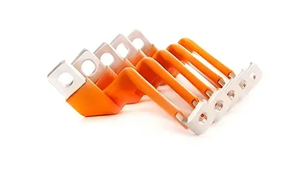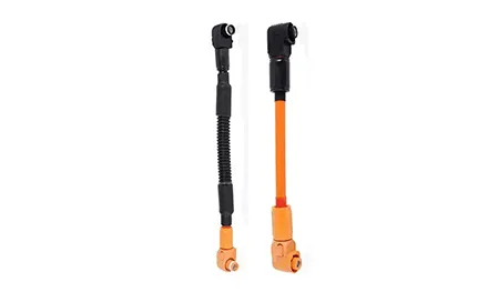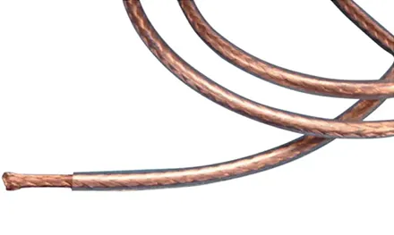


A Flexible Busbar carries the same current as a rigid bar of equivalent cross-section, but it does so through a stack of thin copper foils rather than a single solid block. That layered construction is what allows the conductor to bend, twist, and absorb vibration without cracking. You'll see how the lamination and welding form the conductor, what the insulation options are, and where the current and voltage envelope sits.
A solid bar of the same cross-section carries the same current, but it doesn't bend. The page lists the Flexible Busbar advantages as ultra-high flexibility—bent and drilled, installed in a small space—significantly reduced weight, and excellent vibration resistance. Those three properties come from the laminated structure, not from the copper alone. A solid bar that's thick enough to carry 1,000A is stiff enough to resist the routing you need.
The page's specification range covers 24mm² to 1,200mm², with each layer between 0.1mm and 1mm thick. A 1,200mm² conductor built from 0.5mm foils would use roughly 24 layers. The layer count is set by the target cross-section and the foil thickness—more, thinner foils give more flexibility at the same ampacity, while fewer, thicker foils give a stiffer stack.
The conductor starts as a stack of thin copper foils. The page describes the manufacturing process as die-cutting and stacking, followed by molecular expansion welding. The foils are T2 copper, with the option of bare or tinned finish.
The welding is the step that turns the stack into a single conductor at the termination points. Molecular expansion welding joins the foil layers at the ends, where the busbar connects to terminals, while the middle section stays unbonded. That division—rigid at the ends, flexible in the middle—is what allows the busbar to be bolted at both ends while absorbing movement in between.
| Parameter | ZHONGYAN Flexible Busbar (from the product page) |
|---|---|
| Size range | 24mm² – 1,200mm² |
| Foil thickness per layer | 0.1mm – 1mm |
| Nominal voltage | 1000VAC / 1500VDC (IEC and UL) |
| Operating temperature | -25℃ to 105℃ |
| Continuous current | 125A – 2,800A |
| Conductor material | T2 copper, bare or tinned |
| Insulation options | PVC, TPE |
| Bending endurance | >10,000 cycles at 90° bend radius |
| Bend radius (5mm thick incl. insulation) | 50–75mm |
The page specifies a bending endurance of over 10,000 cycles at a 90° bend radius. That's not a one-time installation bend—it's a repeated flexing capability. In a vehicle or a vibrating cabinet, the busbar may flex slightly with every cycle of operation. The laminated structure distributes that flex across many thin foils rather than concentrating it at a single bend line in a solid bar, which is why the endurance figure can be that high.
The conductor is covered with an insulation layer after welding. The page lists extrusion, injection molding, plastic dipping, powder dipping, spraying, and industrial heat shrink tubing as the available insulation processes. The base insulation materials are PVC and TPE, with TPE offering low-smoke halogen-free properties.
The voltage rating is 1000VAC / 1500VDC under both IEC and UL standards, with an operating temperature range of -25℃ to 105℃. Those ratings cover the common battery pack, switchgear, and inverter environments where a flexible conductor replaces a cable harness.
The page notes that for a busbar 5mm thick including insulation, the minimum bend radius is 50–75mm. The insulation is not a thin cosmetic layer—it adds to the total thickness and therefore to the minimum radius the busbar can be bent without stressing the insulation or the conductor. Routing the busbar tighter than that radius risks cracking the insulation or work-hardening the copper foils at the bend.
The page lists a continuous current range of 125A to 2,800A across the 24–1,200mm² size range. That span covers small battery module interconnects through large industrial switchgear connections. The width range of 24mm to 1,200mm is the other dimension that sets the current capacity—a wider busbar carries more current at the same thickness.
Small modules: 24–100mm², covering low-current interconnects
Battery packs: 100–400mm², the common range for EV and storage module links
Switchgear and PCS: 400–1,200mm², for high-current cabinet connections
Voltage: 1000VAC / 1500VDC, IEC and UL rated
Temperature: -25℃ to 105℃, covering outdoor and enclosure conditions
The page lists applications including high and low voltage electrical appliances, vacuum electrical appliances, mining explosion-proof equipment, new energy vehicles, transportation, and new power grid systems. That breadth reflects the fact that the laminated conductor solves a routing problem in any enclosure where a rigid bar won't fit and a cable harness is too bulky or too prone to vibration failure.
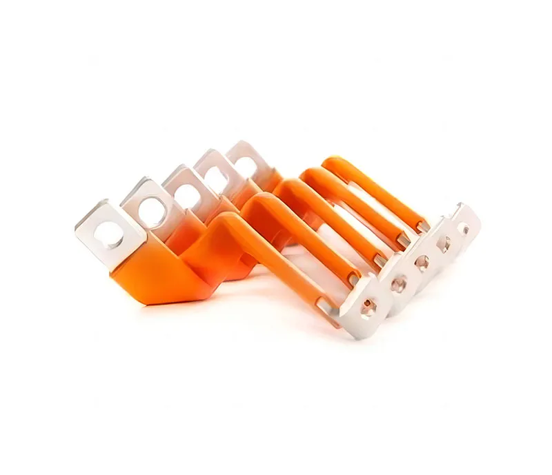
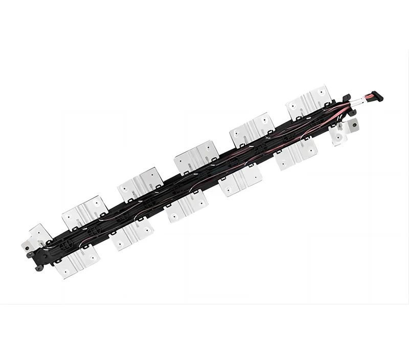
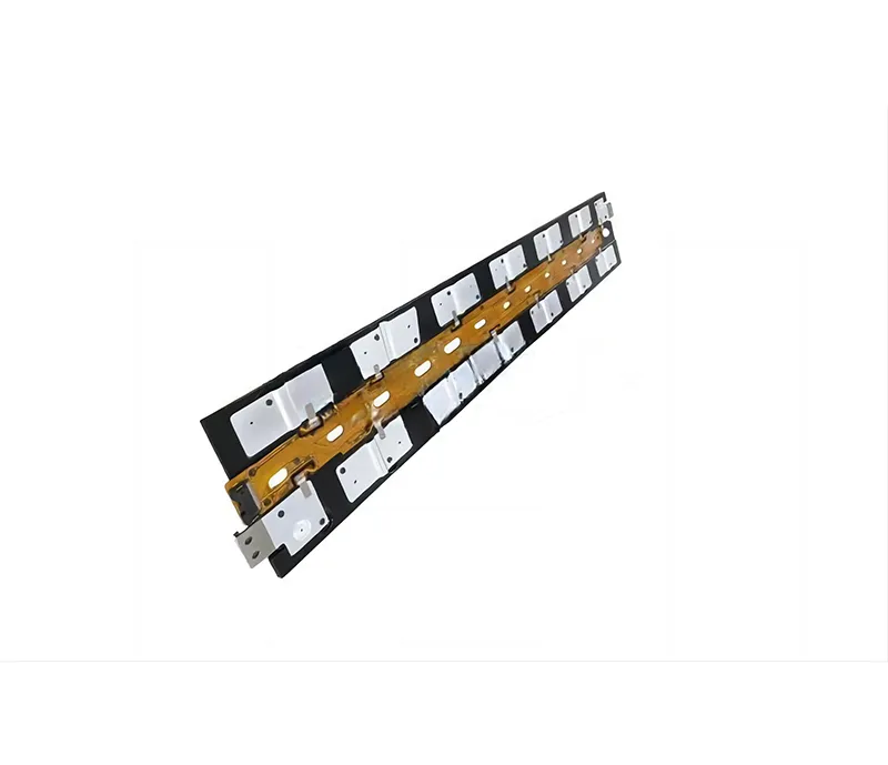
The Flexible Busbar from Zhejiang ZHONGYAN New Energy is built around the laminated conductor the page describes: die-cut and stacked T2 copper foils, molecular expansion welded at the terminations, and insulated with PVC or TPE through extrusion, molding, or heat-shrink processes. The size range of 24–1,200mm², voltage rating of 1000VAC/1500VDC, and current range of 125–2,800A cover the common battery, switchgear, and industrial connection points. The customization path accepts customer drawings and returns a technical evaluation and samples before production. For a system integrator or a pack designer, the value sits in the layered construction—the busbar carries the current of a solid bar while bending to fit the routing envelope, and the welded terminations keep the connection rigid where it needs to be.
Confirm the continuous current against the 125–2,800A range, the voltage against the 1000VAC/1500VDC rating, and the routing envelope against the minimum bend radius of 50–75mm for a 5mm-thick assembly. Check the insulation material against the temperature and fire requirements of the installation, and the termination style against the terminal interface. The page's specification range gives the starting point; the actual pack layout and current profile determine the cross-section and foil count.
Send over your continuous current, voltage class, routing envelope, and termination requirements—we'll help you check them against the 24–1,200mm² size range, 125–2,800A current envelope, and the laminated conductor construction. Talk to ZHONGYAN New Energy about your Flexible Busbar requirements and get a specification-level answer before you commit to the design.
GET A QUOTE


 中文
 English
 Pусский
 Français
 Español