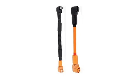


An energy storage connector is the point where battery modules meet the rest of the system, so it carries continuous DC load while staying locked and protected. You'll see what the role demands, how materials and manufacturing shape reliability, and what to check before specifying one for your build.
The core job is reliable power transfer under load. A purpose-built connector uses high current capacity and a secure locking mechanism so the mated pair stays seated through cycling and vibration. That combination is what separates an ESS-rated part from a general-purpose terminal.
Battery packs don't all use the same chemistry, and a connector that only mates cleanly with one formulation forces extra part numbers into the BOM. A connector designed for compatibility with various battery chemistries lets procurement standardize on fewer components while still matching the pack on the bench.
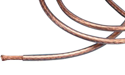
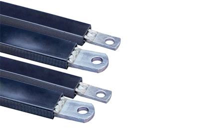
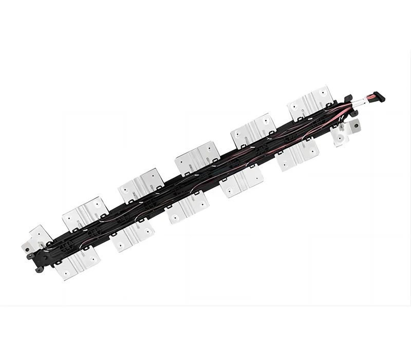
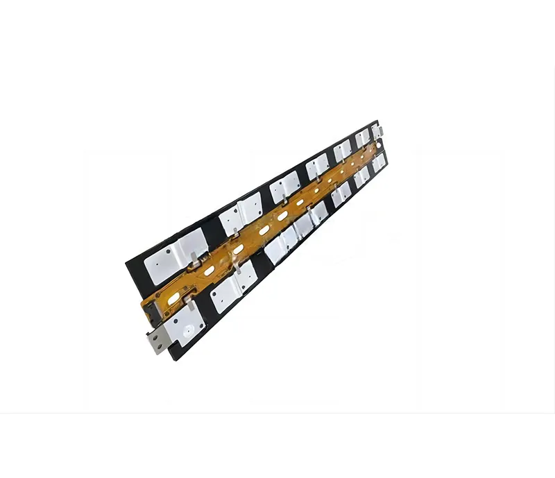
The contact is where the electrical work happens, and the base material sets the ceiling for conductivity and heat tolerance. Copper and aluminum profiles are both in play, shaped through die-cutting, stacking, and molecular expansion welding rather than simple crimping. That welding approach joins conductor surfaces at the molecular level, which supports a low-resistance path across the joint.
Insulation gets equal attention. Extrusion, injection molding, plastic dipping, powder dipping, spraying, and industrial heat shrink tubing are all listed as available processes, so the outer layer can be matched to the housing geometry rather than forced into a one-size shell. For a connector that sits inside a battery rack or a power conversion cabinet, that fit matters as much as the metal inside.
A mechanically crimped joint can develop resistance over time as surfaces shift under thermal cycling. A welded joint removes that interface, so the conductive path stays continuous. The manufacturing sequence—die-cutting, stacking, then molecular expansion welding—isn't decorative; it's the reason the connector can claim reliable power transfer across its service window.
A connector that passes bench tests but backs out in the cabinet is a liability. The secure locking mechanism is the feature that keeps the mated pair engaged when the cable is dressed, when the rack is serviced, and when the system cycles through thermal expansion and contraction.
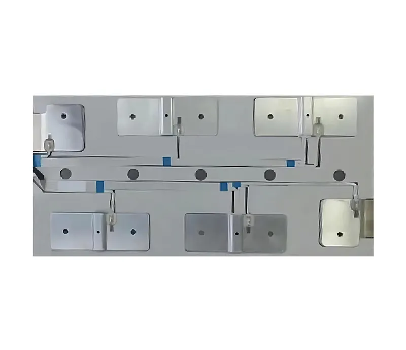
Shape flexibility supports that goal. Customized shapes and irregular-shape processing mean the connector body can follow the routing envelope instead of forcing the cable into an awkward bend. A cleaner cable path reduces strain at the mating interface, which in turn protects the locking feature from being worked loose by side loads.
It should mean the connector doesn't rely on friction alone. The lock needs to engage with a deliberate action and stay engaged until deliberately released—so a service technician can trust that a mated pair won't separate because a cable was nudged during maintenance.
Energy storage isn't a single installation type. The same connector family may land in high and low voltage electrical appliances, vacuum electrical appliances, mining explosion-proof equipment, new energy vehicles, transportation systems, and new power grid systems, according to the product page's listed applications. That breadth is a signal about how the part is built: it has to tolerate different housing environments, different cable entry angles, and different service routines without changing its core function.
The table below maps the listed capability areas to what they mean at the specification stage.
| Listed capability | What it supports at specification |
|---|---|
| High current capacity | Continuous DC transfer between modules and system components |
| Secure locking mechanism | Mated pairs stay seated through cycling, service, and vibration |
| Compatibility with various battery chemistries | Fewer part numbers across mixed-chemistry packs |
| Copper and aluminum profiles | Conductive path matched to current and thermal load |
| Molecular expansion welding | Low-resistance joint without a mechanical interface |
| Customized shapes and irregular-shape processing | Connector body follows the cable routing envelope |
Confirm the connector's current and voltage class against the pack's operating envelope.
Verify the locking action is deliberate and releasable, not friction-dependent.
Check that the housing shape matches the cable entry angle and available bend radius.
Confirm the contact material and joint method suit the expected cycling profile.
Ask whether custom shapes or irregular processing are available if the routing envelope is tight.
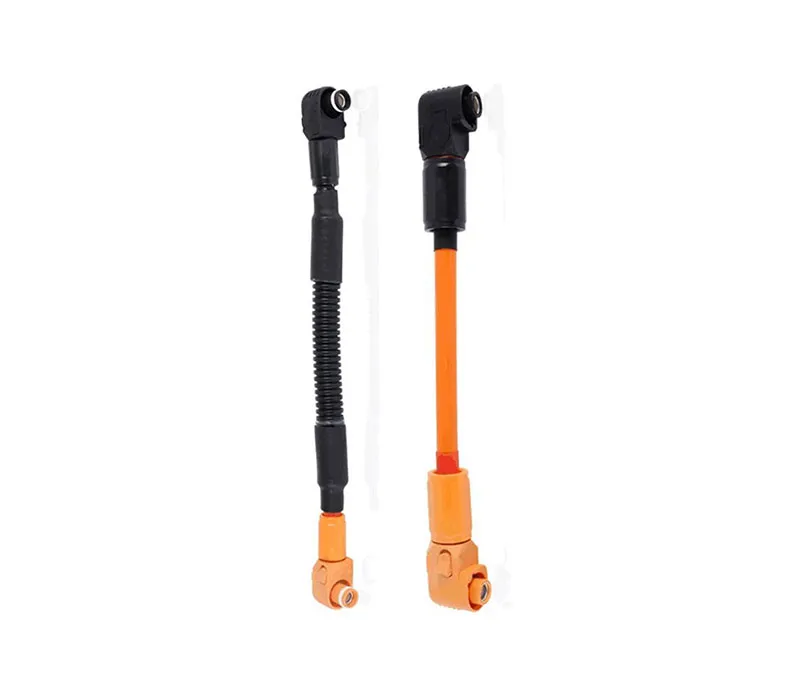
The FJ6Cn HV Connector For Energy Storage System is built around the same priorities the page lists: reliable power transfer between battery modules and storage systems, a secure locking mechanism, and compatibility across battery chemistries. Zhongyan New Energy produces it through a digital production line that handles copper and aluminum profile manufacturing, molecular expansion welding, and multiple insulation processes, with customized shapes available when the routing envelope calls for an irregular form. For a system integrator, that means the connector can be specified as a purpose-built link rather than adapted from a generic terminal—and the customization path (send drawings, receive technical evaluation, then samples) keeps the part aligned to the actual pack layout instead of forcing the layout to fit a catalog shape.
A connector is a small line item with an outsized failure cost. Confirm the production process behind the contact, the locking feature's engagement method, and whether custom geometry is available for your cable routing. Those three answers tell you more about long-term fit than a single current rating on a datasheet.
Send over your battery module layout, cable routing constraints, and current class—we'll help you confirm whether the FJ6Cn HV Connector is the right fit or whether a custom shape is the better path. Talk to Zhongyan New Energy about your energy storage connector requirements and get a technical evaluation before you commit to a BOM line.
GET A QUOTE

 中文
 English
 Pусский
 Français
 Español