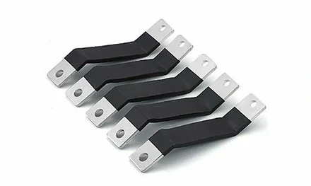


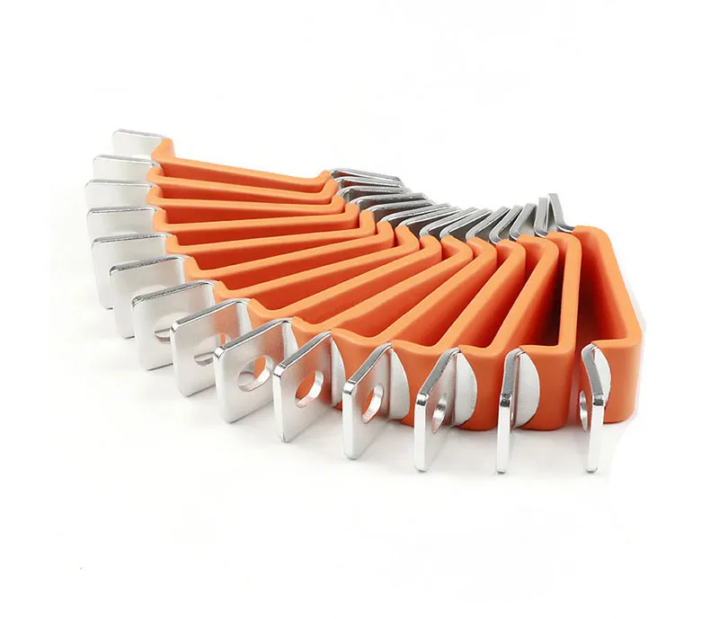
An engineer opens a control cabinet. Cables run every which way, each requiring a lug, a crimp, and careful routing around obstacles. The next project uses a Flexible Busbar instead—flat, layered, and ready to bolt directly into place. Flexible busbars, also known as insulated flexible copper bars, are made from multiple thin layers of electrolytic copper or aluminum stacked and bonded together, then insulated with a high-resistance, flame-retardant material. This construction gives them unique characteristics for power distribution in electric vehicles, renewable energy systems, and industrial machinery. This guide explains how the laminated design works, why it can be routed into spaces that cables cannot easily reach, and what to specify when ordering.
A Flexible Busbar gains its bending ability from a multilayer “sandwich” design. Instead of a single solid conductor or stranded cable, thin foils of copper (typically 0.05–0.20 mm per layer) are stacked and bonded using laser welding or resistance welding. Each layer is separated by a thin dielectric insulating material, forming a compact, flat structure that can be bent, folded, or twisted with a small radius.
Why cables are less flexible. A round cable has a solid or stranded core that resists bending, especially at larger gauges. To achieve a tight bend, the cable must be looped, which consumes more space. The flat, layered busbar can be bent in the plane of the layers with a radius as small as 5–10 times its thickness, allowing it to follow the contours of cabinets and battery modules.
Low inductance as a side benefit. When multiple conductors are stacked with insulation between them, the magnetic fields from opposing currents partially cancel each other. This results in very low effective inductance, which reduces voltage overshoots during fast switching—an advantage for EV inverters and DC‑DC converters.
Efficient heat dissipation. A flat busbar has a larger surface area relative to its cross‑section than a round cable, promoting better heat transfer. This allows the busbar to carry a given current with less copper, which can reduce material weight and cost.
The flat shape of a flexible busbar fits neatly against panels and allows parallel runs with minimal separation. This can reduce the overall footprint of a control cabinet or battery interconnect system. In a typical battery pack, for example, flexible busbars can be routed between cell terminals with only a few millimeters of clearance, whereas cables would require additional space for connectors and bend radii. Similarly, in switchgear, busbars can be stacked vertically with thin insulation between them, achieving a much higher power density than round cable bundles.
| Feature | Cable | Rigid Busbar | Flexible Busbar |
|---|---|---|---|
| Shape | Round | Fixed flat | Bendable flat |
| Bending radius | Large | Not applicable | Very small |
| Heat dissipation | Moderate | Good | Excellent (large surface) |
| Installation | Lugs + crimping | Bolted joints | Direct bolt or clamp |
| Space use | Less efficient | Efficient | Very efficient (conforms to shape) |
| Inductance | Higher | Low | Very low (layered) |
Installing a flexible busbar is straightforward and requires fewer components. No lugs need to be crimped, no heat shrink applied, and no multiple torque checks on separate terminals. Connections are made by punching or drilling the busbar end and bolting directly to the device terminal.
Fewer components to stock. A cable assembly requires cable, lugs, heat shrink, and possibly terminal blocks. A flexible busbar is a single part number that includes the conductor and insulation, simplifying inventory.
Consistent connection quality. Factory‑fabricated busbars have punched holes at precise locations, ensuring repeatable contact pressure when torqued correctly. This reduces the risk of loose connections that cause overheating.
Adaptability to misalignment. Rigid busbars require exact alignment of mounting holes. A flexible busbar can accommodate a few millimeters of offset by bending slightly, avoiding the need for shims or re‑drilling—useful in retrofits where existing hole patterns are not perfectly matched.
When specifying a Flexible Busbar, several parameters should be considered. Cross‑sectional area determines current rating; typical ranges span from 19.5 mm² to 1200 mm², with continuous currents from 125 A up to 2800 A. Material choices include tinned electrolytic copper (standard) or aluminum for weight‑sensitive applications. Insulation should be high‑resistance, halogen‑free, flame‑retardant, and low‑smoke; the insulation covers only a portion of the conductor surface (typically less than 20% contact) to preserve flexibility. Temperature ratings are commonly up to 105°C for the conductor, with insulation rated accordingly. Many flexible busbars carry UL certifications such as UL 67, UL 758, and UL 891. For high‑frequency applications (e.g., IGBT bus links), the laminated construction mitigates skin effect by distributing current across multiple thin layers.
Q: Can a flexible busbar be used outdoors? A: Yes, provided the insulation is UV‑resistant and the terminations are protected from moisture. For outdoor cabinets (NEMA 3R or higher), standard flexible busbars with sealed terminations work well. For direct exposure, specify a busbar with a fully insulated jacket.
Q: How do I size a flexible busbar for my current load? A: Start with the manufacturer‘s current rating tables. Ambient temperature and bundling affect ampacity. As a general guideline, a 10 mm × 1 mm copper cross‑section carries approximately 25 A in free air at 40°C ambient. For a 500 A application, a 50 mm² cross‑section is a good starting point, but always verify with the manufacturer’s specific data.
Q: Can I bend a flexible busbar in the field? A: Yes, but follow the manufacturer‘s minimum bending radius. Bending it sharply can separate the internal laminations or crack the insulation. If you need a complex shape, order the busbar pre‑formed from the factory. Most suppliers offer custom bending services.
Q: What is the expected service life of a flexible busbar? A: In normal operating conditions (‑40°C to +105°C, non‑corrosive environment), the copper or aluminum conductor itself does not degrade. The insulation may age over time, typically 10–20 years depending on temperature and UV exposure. Flexible busbars used in indoor electrical panels often outlast the equipment they serve.
When a power distribution system requires high current, limited space, and vibration resistance, the Insulated Busbars product line provides a ready solution. These flexible busbars are manufactured from electrolytic copper (99.9% purity) or aluminum, with a multilayer laminated construction that achieves low inductance and excellent heat dissipation. The insulation is flame‑retardant, halogen‑free, and rated for operation from –40°C to +105°C.
Available cross‑sections range from 19.5 mm² to 1200 mm², supporting continuous currents from 125 A to 2800 A. Standard terminations include punched bolt holes, but custom termination styles—such as fork terminals, ring lugs, or direct PCB‑mount tabs—are available for OEM applications. The flexible busbars are UL recognized and RoHS compliant.
For engineers designing battery packs, inverters, switchgear, or renewable energy systems, the Insulated Busbars flexible busbar offers a compact, reliable alternative to traditional wiring methods. The product is backed by technical datasheets, 3D CAD models, and application engineering support to ensure correct specification and installation.
→ Request a quote from the supplier for Insulated Busbars — Share your required current rating (A), operating voltage (V), available space dimensions, and any environmental constraints (temperature, humidity, vibration). Their application engineers will recommend the optimal cross‑section, number of layers, and termination style for your project.
GET A QUOTE