


Your power distribution system is running at full capacity, and the thermal camera shows a hot spot at the busbar connection. The equipment hasn‘t failed yet, but the temperature rise is concerning. You’re not sure whether to tighten the connection, replace the busbar, or call for a full system shutdown. Before you take drastic action, understand that a Composite Laminated Busbar is designed to be flexible, easy to install, and durable. Overheating at a connection point rarely means the busbar itself is defective—it usually points to a specific installation or environmental issue that can be diagnosed and fixed without replacing the entire component. This guide walks through the most common causes of busbar connection overheating, how to identify each one by looking at the pattern of the problem, and the adjustments that will restore reliable operation.
The location and pattern of overheating reveal the root cause before you touch any component.
Heat concentrated at the terminal interface. The temperature spike is localized exactly where the busbar connects to the terminal block or device. This points to insufficient contact pressure, surface contamination, or misalignment between the busbar terminal and the mating surface.
Heat distributed along the busbar surface. The entire busbar runs warm, not just the connection point. This suggests the busbar is undersized for the current load, or ambient temperature in the enclosure exceeds the design range.
Intermittent temperature spikes that come and go. The connection runs cool for hours, then suddenly heats up, then cools again. This indicates a loose mechanical connection that expands and contracts with thermal cycling—the most dangerous failure mode because it can cause arcing.
Localized hot spot away from terminals. Heat appears at a bend or transition point in the busbar. This indicates mechanical stress on the laminated layers, possibly from overtightening during installation or from the busbar being forced into position against its natural flex direction.
The most common source of busbar connection overheating is improper installation technique. The Composite Laminated Busbar is designed to be easy to install, but that ease can lead to rushed workmanship that skips critical steps. Before connecting the busbar, clean the terminal contact surfaces using a lint-free cloth with high-purity isopropyl alcohol, wiping both the busbar terminal and the mating device terminal. Ensure no oil, oxide layer, or dust remains, and allow the alcohol to fully evaporate. Confirm that the terminal surfaces are flat and free of burrs. Use a torque wrench to tighten the mounting screws or bolts to the manufacturer‘s specified value. Over‑tightening distorts the busbar terminal and cracks the laminated structure; under‑tightening leaves air gaps that cause arcing. Verify that the busbar is aligned correctly with the device terminals. Forced alignment—bending the busbar to reach misaligned mounting holes—creates mechanical stress that increases contact resistance at the terminal. The flexibility of the composite busbar allows for easy bending and routing around obstacles, but this flexibility is for routing the busbar body, not for forcing misaligned terminals. If the mounting holes don‘t line up, reposition the device or use a properly sized busbar rather than forcing the connection.
Even when installation seems correct, underlying issues with contamination, torque application, or connector condition can cause overheating.
Surface contamination. Dust, oxide layers, or oil residue on terminal surfaces increase contact resistance. This resistance converts electrical energy into heat, creating a localized hot spot. This is especially problematic in environments with airborne contaminants such as factories with metal dust or chemical plants.
Incorrect torque application. When technicians use hand feel instead of a torque wrench, the actual tightening force varies widely. A single under‑tightened bolt in a multi‑bolt connection can carry disproportionate current, heat up, and fail.
Worn or damaged mating connectors. The device side of the connection (such as an IGBT terminal or battery post) may have worn plating or surface pitting from previous connections. Even a perfect busbar terminal cannot compensate for a damaged mating surface.
Missing or damaged insulating washers. In designs where insulating hardware separates conductive paths, a missing or cracked insulating washer can create an unintended current path, causing localized heating and potentially short circuits.
The busbar itself may be perfectly installed, but external conditions can still cause overheating. High ambient temperature inside the enclosure reduces the busbar‘s current-carrying capacity. A busbar rated for 300A at 40°C ambient may overheat at 250A if the enclosure temperature reaches 60°C. Poor airflow around the busbar traps heat. The laminated structure relies on convection to dissipate heat; when the busbar is tightly packed against other components or the enclosure wall, heat accumulates. In these cases, the solution is not to replace the busbar but to improve cooling—add enclosure ventilation fans, increase spacing between power components, or reduce the load. High humidity or exposure to corrosive chemicals accelerates oxidation at connection points, increasing contact resistance over time. For applications in wet or chemically aggressive environments, specify a busbar with enhanced corrosion protection.
Before opening the enclosure and disconnecting anything, use non‑invasive diagnostic methods to narrow down the cause.
Thermal imaging. Scan the entire busbar assembly while the system is under normal load. Compare terminal temperatures against the busbar body temperature. A terminal that is more than 15–20°C hotter than the adjacent busbar surface indicates a connection problem. Uniform heating across the busbar suggests overload or ambient temperature issues.
Voltage drop measurement. With the system operating, measure the voltage drop across each connection point using a precision multimeter. Excessive voltage drop (typically above 10–20 mV for high‑current connections) indicates high resistance at that interface. Compare measurements across identical connections to identify outliers.
Acoustic inspection. A loose connection carrying high current may produce a faint buzzing sound from micro‑arcing. Listen near the busbar during operation. If you hear intermittent sizzling or buzzing, shut down immediately—this is a pre‑failure warning.
Prevention is always more cost‑effective than troubleshooting after failure. Follow these practices for every busbar installation. Inspect the busbar before installation—confirm that the Composite Laminated Busbar has no visible delamination, cracks, or deformation. Clean all terminal surfaces. Torque all fasteners to specification using a calibrated torque wrench; never rely on hand feel. Use the correct fastener type—stainless steel bolts in corrosive environments, zinc‑plated steel for general use. Apply anti‑seize compound only if specified by the manufacturer. Ensure the busbar is supported along its length, not just at the terminals, to prevent mechanical stress from weight or vibration. The composite structure is durable, but excessive cantilevered weight can stress the terminals. Record torque values and thermal images after installation to establish a baseline for future troubleshooting. Periodic re‑torqueing after the first thermal cycle is recommended, as initial bolt stretch may settle after the system reaches operating temperature.
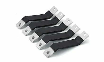
When installed correctly, a Composite Laminated Busbar delivers performance that traditional cable bundles cannot match. The flexible design allows for easy routing around enclosure obstacles and simplifies wiring. The composite construction is durable, resistant to wear and tear, and ensures long‑lasting performance even in demanding industrial environments. By eliminating multiple cable terminations, composite busbars reduce the number of potential failure points in the power distribution system, improving overall system reliability.
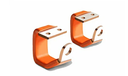
Laminated busbars effectively reduce stray inductance compared to traditional cables. Because the positive and negative conductors are separated by only a thin dielectric layer, the magnetic fields cancel each other, drastically reducing parasitic inductance. This low-inductance characteristic prevents voltage spikes during high-speed switching, protects sensitive power semiconductors, and enables cleaner power delivery. The flat, layered structure allows for much denser packing of circuits within a cabinet—space savings of 30% to 50% are common compared to traditional wiring—freeing up valuable real estate for other components or airflow.
Q: Can I bend a composite laminated busbar after installation if access is tight?
A: The busbar is designed to be flexible during installation, allowing it to be routed around obstacles. However, repeated bending or bending beyond the manufacturer‘s recommended radius can stress the laminated layers and cause delamination. Perform all bending during initial installation before final torquing.
Q: How do I clean a busbar connection that has already overheated?
A: Disconnect power, unbolt the busbar, and inspect both terminal surfaces. If the surface has light discoloration, clean with isopropyl alcohol and a lint-free cloth. If there is pitting or carbonization from arcing, the terminal surface may be damaged beyond repair. In that case, replace the busbar—a repaired connection will never have the same current-carrying capacity.
Q: What is the expected service life of a composite laminated busbar?
A: Under normal operating conditions with proper installation and maintenance, the conductive layers (copper or aluminum) have an indefinite service life. The insulating layers can last 10–20 years depending on thermal cycling and environmental exposure. The durability of the composite structure ensures long-lasting performance, and regular thermal imaging checks can detect degradation before failure.
Q: Can I use the same busbar for both AC and DC applications?
A: Yes. The low-inductance design of laminated busbars benefits both AC and DC systems, but the current rating may differ between AC and DC due to skin effect and DC derating factors. Consult the manufacturer’s specifications for the specific busbar model.
Q: Does Haiyan New Energy offer custom busbar configurations?
A: Yes. Haiyan New Energy positions itself as a reliable partner for busbar production, offering custom busbar solutions tailored to specific system requirements. Contact their team directly with design specifications for a customized quote.
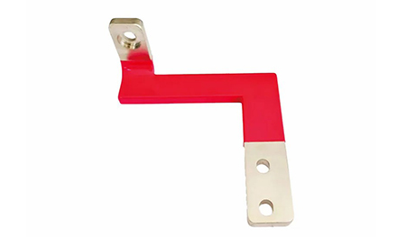
When power distribution reliability depends on consistent connections, the quality of the busbar determines the long‑term performance of the entire system. Haiyan New Energy manufactures high‑performance Composite Laminated Busbars designed for flexibility, ease of installation, and reliable electrical connections across a wide range of applications from residential to industrial settings. The flexible design allows for easy bending and routing around obstacles, while the composite construction ensures durability and long‑lasting performance even in demanding environments. By combining multiple conductive layers with thin dielectric insulation, Haiyan‘s busbars achieve the low inductance and high current‑carrying capacity required for modern power electronics, from EV battery packs and solar inverters to telecommunications equipment and industrial power distribution systems.
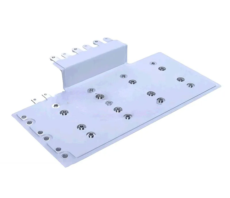
Haiyan New Energy offers custom busbar solutions, with the engineering team working directly with customers to develop tailored configurations based on current rating, voltage, and dimensional constraints. For engineers and facility managers dealing with recurring connection overheating problems, upgrading to a properly specified composite laminated busbar—installed with the correct torque and surface preparation—eliminates a common source of downtime. Their products are manufactured to meet applicable industry certifications, ensuring compliance with safety and performance standards for global markets.
→ Request a quote from Haiyan New Energy for the high performance Laminated Busbars — Share your system voltage, continuous current rating, available space dimensions, and terminal configuration requirements. Their engineering team will recommend the right busbar specification and provide installation guidance.
GET A QUOTE